Saturday, January 11, 2014

Thevenin and Norton Equivalent Circuit

Thevenin's & Norton Equivalent Circuit

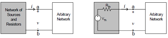
Thevenin's Equivalent Theorem

- Thévenin’s theorem, as stated for sinusoidal AC circuits, is changed only to include the term impedance instead of resistance.

- Any two-terminal linear ac network can be replaced with an equivalent circuit consisting of a voltage source and an impedance in series.

- VTh is the Open circuit voltage between the terminals a-b.

- ZTh is the impedance seen from the terminals when the independent sources are
set to zero.

**Take note that: VTh is the Open circuit voltage between the terminals a-b while ZTh is the impedance seen from the terminals when the independent sources are set to zero**


Norton's Equivalent Theorem

 - The linear circuit is replaced by a current source in parallel with an impedance. IN is the Short circuit current flowing between the terminals a-b when the terminals are short circuited. 

 - In Norton’s theorem, it states that a linear two-terminal circuit can be replaced by an equivalent circuit consisting of a current source IN in parallel with a resistor RN, where IN is the short-circuit current through the terminals and RNis the input or equivalent resistance at the terminals when the independent sources are turned off.


Thevenin and Norton equivalents are related by:


In Thevenin's and Norton's Equivalent Theorem, This is good if we are going to put concentration on a particular part of a circuit so that in other part in other way around, The circuit can be replaced by using Thevenin's equivalent.

Source Transformation

Source Transformation

Transform a voltage source in series with an impedance to a current source in parallel with an impedance for simplification or vice versa.


Practice Problem : Calculate the current Io.


If we transform the current source to a voltage source, we obtain the circuit


In source transformation, I observed and i learned that using this theorem will simplify the circuit given for us to be able to convert it into more easier form that it can be, In such way, The circuit will appear simple. 


Friday, December 6, 2013

Nodal and Mesh Analysis of Phasor Circuit


Nodal Analysis
  • Since KCL is valid for phasors, we can analyze AC circuits by NODAL analysis.
  • Determine the number of nodes within the network.
  • Pick a reference node and label each remaining node with a subscripted value of voltage: V1, V2 and so on.
  • Apply Kirchhoff’s current law at each node except the reference. Assume that all unknown currents leave the node for each application of Kirhhoff’s current law.
  • Solve the resulting equations for the nodal voltages.
  • For dependent current sources: Treat each dependent current source like an independent source when Kirchhoff’s current law is applied to each defined node. However, once the equations are established, substitute the equation for the controlling quantity to ensure that the unknowns are limited solely to the chosen nodal voltages.
Since KCL is valid for phasors, we can analyze AC circuits by NODAL analysis.

Sample Problem no.1 :
Find v1 and v2 using nodal analysis


- - - - - - - - - - - - - - - - - - - - - - - - - - - - - - - - - - - - - - - - - - - - - - - - -


Mesh Analysis

Since KVL is valid for phasors, we can analyze AC circuits by MESH analysis.


Sample Problem 2:
Calculate the current Io


Saturday, November 16, 2013

Phasors

Phasor Diagrams

In AC electrical theory every power source supplies a voltage that is either a sine wave of one particular frequency or can be considered as a sum of sine waves of differing frequencies. The neat thing about a sine wave such as V(t) = Asin(ωt + δ) is that it can be considered to be directly related to a vector of length A revolving in a circle with angular velocity ω - in fact just the y component of the vector. The phase constant δ is the starting angle at t = 0.


Since a pen and paper drawing cannot be animated so easily, a 2D drawing of a rotating vector shows the vector inscribed in the centre of a circle as indicated below. The angular frequency ω may or may not be indicated.


When two sine waves are produced on the same display, one wave is often said to be leading or lagging the other. This terminology makes sense in the revolving vector picture as shown in Figure 3. The blue vector is said to be leading the red vector or conversely the red vector is lagging the blue vector.


Considering sine waves as vertical components of vectors has more important properties. For instance, adding or subtracting two sine waves directly requires a great deal of algebraic manipulation and the use of trigonometric identities. However if we consider the sine waves as vectors, we have a simple problem of vector addition if we ignore ω. For example consider

Asin(ωt + φ) = 5sin(ωt + 30°) + 4sin(ωt + 140°) ;
the corresponding vector addition is:


Ax = 5cos(30° + 4cos(140°) = 1.26595Ay = 5sin(30° + 4sin(140°) = 5.07115
Thus

and


So the Pythagorean theorem and simple trigonometry produces the result
5.23sin(ωt + 76.0°) .
Make a note not to forget to put ωt back in!

Phasors and Resistors, Capacitors, and Inductors
The basic relationship in electrical circuits is between the current through an element and the voltage across it. For resistors, the famous Ohm's Law gives

VR = IR .                     (1)

For capacitors
VC = q/C .                 (2)

For inductors
VL = LdI/dt .             (3)

These three equations also provide a phase relationship between the current entering the element and the voltage over it. For the resistor, the voltage and current will be in phase. That means if I has the form Imaxsin(ωt + φ) then VR has the identical form Vmaxsin(ωt + φ) where Vmax = ImaxR. For capacitors and inductors it is a little more complicated. Consider the capacitor. Imagine the current entering the capacitor has the form Imaxsin(ωt + φ). The voltage, however, depends on the charge on the plates as indicated in Equation (2). The current and charge are related by I = dq/dt. Since we know the form of I simple calculus tells us that q should have the form − (Imax/ω)cos(ωt + φ) or (Imax/ω)sin(ωt + φ - 90°). Thus VC has the form (Imax/ωC)sin(ωt + φ - 90°) = Vmaxsin(ωt + φ - 90°). The capacitor current leads the capacitor voltage by 90°. Also note that Vmax = Imax/ωC. The quantity 1/ωC is called the capacitive reactance XC and has the unit of Ohms. For the inductor, we again assume that the current entering the capacitor has the form Imaxsin(ωt + φ). The voltage, however, depends on the time derivative of the current as seen in Equation (3). Since we assumed the form of I, then the voltage over the inductor will have the form ωLImaxcos(ωt + φ) or Vmaxsin(ωt + φ + 90°). The inductor current lags the inductor voltage. Here note that the quantity ωL is called the inductive reactance XL. It also has units of Ohms.
The phase relationship of the three elements is summed up in the following diagram,


Note that in all three cases, resistor, capacitor, and inductor, the relationship between the maximum voltage and the maximum current was of the form


Vmax = ImaxZ .                     (4)


We call Z the impedance of the circuit element.  Equation (4) is just an extension of Ohm's Law to AC circuits.  For circuits containing any combination of circuit elements, we can define a unique equivalent impedance and phase angle that will allow us to find the current leaving the battery.  We show how to do so in the next section.


Phasors and AC Circuit Problems
Phasors reduce AC Circuit problems to simple, if often tedious, vector addition and subtraction problems and provide a nice graphical way of thinking of the solution. In these problems, a power supply is connected to a circuit containing some combination of resistors, capacitors, and inductors. It is common for the characteristics of the power supply, Vmax and frequency ω, to be given. The unknown quantity would be the characteristics of the current leaving the power supply, Imax and the phase angle φ relative to the power supply. To solve one needs only to follow the rules:
  1. Circuit elements in parallel share the same voltage.
  2. Circuit elements in series share the same current.
  3. Do one branch of the circuit at a time.
  4. Maintain the phase relationships given in Figure 5.
  5. Use Ohm's Law V = IZ where Z is the equivalent impedance of any combination of circuit elements being considered.


Tuesday, October 15, 2013

Thevenin's Theorem

• Thevenin’s Theorem is a very important and useful theorem.
• It is a method for the reduction of a portion of a complex circuit into a simple one.
• It reduces the need for repeated solutions of the same sets of equations.

Thevenin Equivalent Circuit
Any two-terminal linear network, composed of voltage sources, current sources, and resistors, can be replaced by an equivalent two-terminal network consisting of an independent voltage source in series with a resistor.


Superposition Theorem

Superposition Theorem statement:

The theorem states: “In a network with two or more sources, the current or voltage for any component is the algebraic sum of the effects produced by each source acting separately”

•This means that regardless of the source, we have to analyze them one at a time.
•Things to remember:
–Voltage sources will be shorted
–Current sources will be opened
•For these examples, we will stay with voltage sources


First circuit to consider:


Algebraically sum the results
•VP = VR1 + VR2 = 6V + -12V = 6V – 12V = -6V


Algebraically add the values
•VP = VR1 + VR2 = -30V + 20V = -10V

If the resistors were reversed, the overall value of VP would remain the same but the polarities would be reversed. This is due to R2 now being the larger in the voltage divider ratio when calculating the values.


Nodal & Mesh Analysis

NODAL ANALYSIS:


Steps to Determine Node Voltages

• Select a node as the reference node. Assign voltages v1, v2, · · · , vn − 1
to determine the remaining n − 1 nodes.
The voltages are referenced with respect to the reference
(datum) node (ground).
• Apply KCL to each of the n − 1 non-reference nodes. Use Ohm’s
law to express the branch currents in terms of node voltages.
• Solve the resulting simultaneous equations to obtain the unknown
node voltages.


Nodal Analysis with Voltage Sources

• Voltage source between reference node and a non reference node.
Set the voltage of the non reference node to that of the voltage
source.
• Voltage source between two non reference nodes.
Form a supernode (generalized node) and apply both KVL and
KCL to determine the node voltages.
A supernode is formed by enclosing a (dependent or independent)
voltage source connected between two non reference nodes
and any elements connected in parallel with it.
Properties of a supernode:


BASIC NODAL AND MESH ANALYSIS
– The voltage source inside the supernode provides a constraint
equation needed to solve for the node voltages.
– A supernode has no voltage of its own.

– A supernode requires the application of both KCL and KVL.


MESH ANALYSIS:
-A mesh is a loop that does not contain any other loops within it.

Steps to determine mesh currents:
• Assign mesh currents i1, i2, · · · , in to the meshes.
• Apply KVL to each of the n meshes. Use Ohm’s law to express
the voltages in terms of the mesh currents.

• Solve the resulting n simultaneous equations to get the mesh currents.


Mesh Analysis with Current Sources
• Current source exists only in one mesh. Here mesh current = ±
current source.
• Current source between two meshes, form ’Supermesh’ by excluding
the current source any element connected in series with it.
• A Supermesh results when two meshes have a (dependent or independent)
current source in common.

Properties of a supermesh
-The current source in the supermesh provides the constraint
equation necessary to solve for the mesh currents.
– A supermesh has no current of its own.

– A supermesh requires the application of both KVL and KCL.


Nodal and Mesh Analysis by Inspection


Gkk = sum of the conductances connected to node k
Gkj = Gjk= negative of the sum of the conductances directly connecting
vk = unknown voltage at node k
ik = sum of all independent current sources directly connected to no
In matrix form, G~v =~i

G is called the conductance matrix.


Rkk = sum of the resistances in mesh k
Rkj = Rjk= negative of the sum of the resistances in common with meshes
ik = unknown mesh current for mesh k in the clockwise direction.
vk = clockwise sum of all independent voltage sources in mesh k, with
In matrix form, R~i = ~v
R is called the resistance matrix.